
circuit board components identification pdf
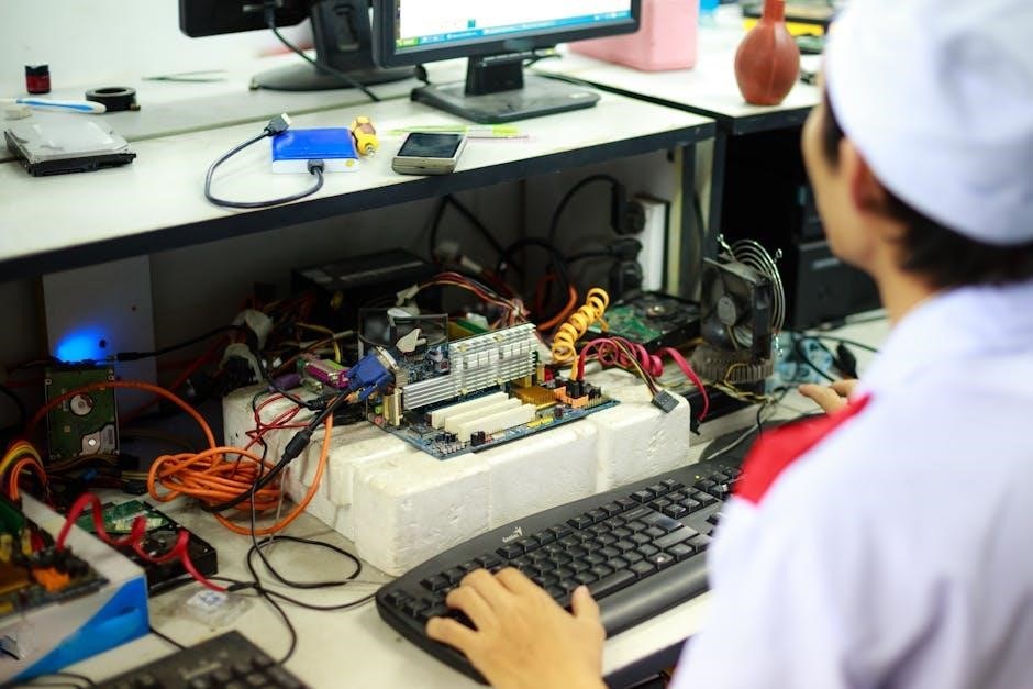
A printed circuit board (PCB) is the backbone of modern electronics, connecting components like resistors, capacitors, and ICs․ Identifying these components is crucial for understanding, troubleshooting, and repairing electronic circuits․
Understanding the PCB Layout and Design
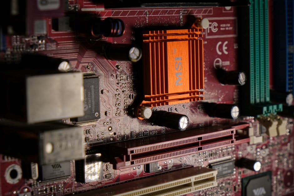
The PCB layout is a critical aspect of electronic design, determining how components are arranged and connected․ It involves creating a blueprint for the board, ensuring proper signal flow and minimizing interference․ The layout includes component footprints, which define the space and connection points for each part, such as resistors or ICs․ Reference designators are assigned to each component, helping identify their locations․ Visual markings, like polarity indicators for capacitors and diodes, aid in assembly and troubleshooting․ The design must balance functionality, manufacturability, and thermal management․ A well-organized layout enhances performance, reduces errors, and streamlines production․ Understanding these principles is essential for designing efficient and reliable PCBs․
Identifying Key Components on a Circuit Board
Resistors, capacitors, inductors, diodes, transistors, and ICs are essential components․ Each has distinct physical features and markings, such as color codes for resistors or polarity signs for capacitors and diodes․
3․1 Resistors
Resistors are fundamental components in electronic circuits, designed to control voltage and current by providing a specific opposition to the flow of electricity․ They are typically identified by their distinctive color bands, which indicate their resistance value and tolerance․ The color coding system is standardized, with each band representing a digit, multiplier, or tolerance․ For example, a red band signifies a value of 2, while a silver band indicates a multiplier of 0․01․ Resistors are categorized into fixed and variable types, with common types including carbon film, metal film, and wirewound resistors․ Their polarity is not a concern, as they are non-polarized components․ Accurate identification of resistors is crucial for circuit functionality and troubleshooting․
3․2 Capacitors
Capacitors are essential components that store electrical energy in an electric field․ They are commonly used for filtering, decoupling, and energy storage in circuits․ Capacitors come in various types, including ceramic, electrolytic, and film capacitors, each with distinct characteristics; Electrolytic capacitors are polarized, with clear markings indicating the positive and negative terminals, often denoted by a minus sign (-) near the negative lead․ Ceramic capacitors are non-polarized and typically smaller, with their capacitance value marked directly on the body․ Capacitor values are usually expressed in microfarads (µF), along with voltage ratings․ Proper identification of capacitors is critical, as incorrect installation can lead to circuit malfunction or component failure․ Their cylindrical or rectangular shapes and color-coded or printed markings aid in easy recognition on a PCB․
3․3 Inductors
Inductors are passive components that store energy in a magnetic field when current flows through them․ They are commonly used for filtering, tuning, and impedance matching in circuits․ Inductors are typically recognizable by their wire coil or ferrite core construction, often wrapped in a cylindrical or rectangular package․ Small inductors may appear as surface-mount devices (SMDs) with minimal visible wiring․ Inductance is measured in henries (H) or microhenries (µH), with values often marked on the component or PCB․ Proper identification is crucial, as inductors play a key role in managing high-frequency signals and preventing electromagnetic interference (EMI)․ Their compact size and specific markings make them easily distinguishable from other components like resistors or capacitors․ Always refer to the PCB’s reference designator for accurate identification and application․
3․4 Diodes
Diodes are essential electronic components that allow current to flow in one direction while blocking it in the opposite direction․ They are crucial for rectification, signal demodulation, and voltage regulation․ Diodes are typically identified by their arrow symbol on the schematic, indicating the direction of conventional current flow․ On a PCB, diodes can be found in either through-hole or surface-mount packages․ Their polarity is often marked with a band or stripe near one end, signifying the cathode side․ Common types include rectifier diodes, Zener diodes, and Schottky diodes, each serving specific functions․ Proper identification ensures correct voltage and current handling, preventing damage to the circuit․ Always verify the component’s polarity to maintain the integrity of the electronic circuit and avoid potential malfunctions or component failure․ Diodes are fundamental in protecting and controlling the flow of electricity within a circuit board․
Transistors are fundamental semiconductor devices used to amplify or switch electronic signals․ They are essential for controlling the flow of electrical current, making them indispensable in modern electronics․ On a PCB, transistors are typically identified by their three terminals: base, collector, and emitter․ Bipolar Junction Transistors (BJTs) and Field-Effect Transistors (FETs) are the most common types․ BJTs are further classified into NPN and PNP, depending on their internal structure․ Transistors are often used in amplifiers, switches, and oscillators․ Their identification involves checking the component’s markings, which usually include the part number․ Proper handling and installation are critical to ensure the transistor operates correctly within the circuit․ Always refer to the datasheet for specific voltage and current ratings to prevent damage․ Transistors play a vital role in enabling electronic circuits to function efficiently․ Integrated Circuits (ICs) are miniature electronic circuits packaged in a single semiconductor material․ They consist of millions of transistors and passive components, enabling complex functions like microprocessing and memory storage․ ICs are identified by their unique numbering and labeling, often with a reference designator starting with ‘U’ on PCBs․ Common types include microcontrollers, memory chips, and logic gates․ ICs are soldered onto the PCB using surface-mount or through-hole techniques․ Their polarity is crucial, with markings indicating pin 1; Proper handling ensures static protection․ ICs are essential for modern electronics, driving advancements in computing, communication, and automation․ Always consult the datasheet for specific pin configurations and operational parameters to ensure correct installation and functionality․ Reference designators are standardized labels assigned to components on a PCB to uniquely identify them․ Typically, they consist of a letter followed by a number, where the letter represents the component type (e․g․, R for resistors, C for capacitors)․ These designators are crucial for matching components to their respective roles in the schematic diagram․ They help technicians trace signals and identify components during assembly or repair․ Proper labeling ensures clarity and reduces errors․ For example, “R1” might refer to a specific resistor, while “U3” could denote an integrated circuit․ This systematic approach enhances documentation and simplifies communication among engineers and technicians․ Always cross-reference designators with the project’s bill of materials for accurate identification․ This practice is essential for maintaining consistency across all stages of PCB design and production․ Accurate labeling is a cornerstone of efficient electronics manufacturing and troubleshooting․ Visual markings on circuit boards are essential for identifying components and their polarities․ Common indicators include “+” and “-” symbols near leads to denote polarized components like capacitors and diodes․ These markings ensure proper installation and prevent damage․ Color codes, such as those on resistors, provide additional information about values and tolerances․ Other components, like transformers or oscillators, may feature distinct shapes or labels (e․g․, “T” for transformers)․ Polarity indicators are critical for ensuring components function correctly and avoid reverse voltage damage․ Always refer to these visual cues when assembling or repairing a PCB to maintain circuit integrity․ These markings are a key part of efficient and accurate component identification․ They simplify troubleshooting and ensure reliable operation of electronic circuits․ Identifying components on a circuit board requires the right tools and techniques․ A multimeter is essential for measuring resistance, voltage, and capacitance, helping to verify component values․ Datasheets provide detailed specifications and pinouts for ICs and other complex components․ Online databases and component identification guides offer visual references for recognizing parts by their shape, color, and markings․ For advanced analysis, techniques like X-ray fluorescence (XRF) can map elemental composition․ Additionally, soldering irons and desoldering tools are necessary for safely removing components for closer inspection․ Magnifying glasses or microscopes can reveal tiny markings on small components․ Proper documentation and organization of components ensure efficient identification and troubleshooting․ These tools and methods are vital for accurately identifying and working with circuit board components․ They streamline the process, reducing errors and improving overall efficiency․ Identifying components on a circuit board can be challenging due to their small size, similar appearances, and complex markings․ Components like capacitors and resistors often look alike, requiring measurements to confirm their values․ Surface-mount technology (SMT) components are particularly difficult to identify due to their tiny size and lack of clear labeling․ Damaged or worn-out markings further complicate identification․ Additionally, the lack of standardized labeling across manufacturers can lead to confusion․ Advanced components, such as integrated circuits (ICs), often require datasheets for proper identification․ Without proper tools or documentation, identifying components can become time-consuming and error-prone․ These challenges highlight the need for careful inspection, reliable resources, and advanced tools to ensure accurate component identification․ Proper training and experience are essential to overcome these obstacles effectively․ Effective documentation and organization of components are essential for streamlined workflows and efficient troubleshooting․ Start by creating a comprehensive list of all components, including their reference designators, values, and locations on the PCB․ Use clear, standardized labeling and maintain detailed records in a centralized database or spreadsheet․ High-quality images or diagrams of the board can serve as visual references․ Organize physical components in labeled containers or bins to prevent mix-ups․ Regularly update documentation to reflect any changes or upgrades․ Implement version control to track modifications over time․ Finally, conduct periodic audits to ensure accuracy and consistency․ These practices enhance clarity, reduce errors, and save time during repairs or upgrades․3․5 Transistors
3․6 Integrated Circuits (ICs)

Reference Designators and Component Labeling

Visual Markings and Polarity Indicators
Tools and Techniques for Component Identification
Common Challenges in Component Identification
Best Practices for Documenting and Organizing Components